Burner Installation.
March 10, 2008
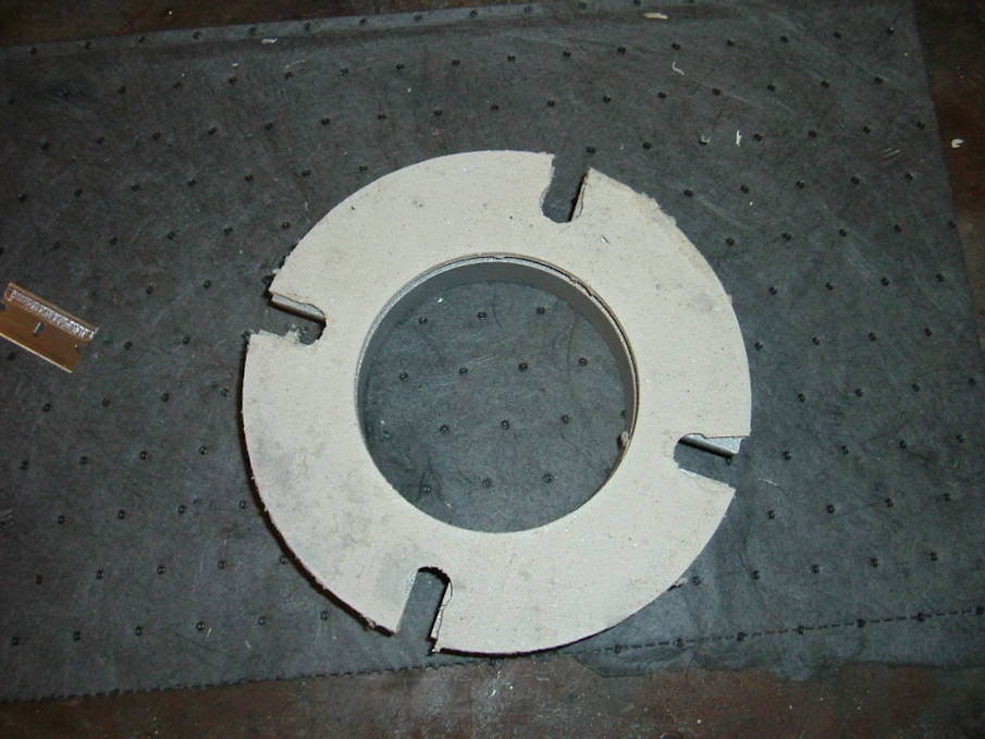
The M12 burner mounting bolts for the mounting flange are to large, a 7/16 bolt and nylock nut was substituted, I also had to drill out the 4 flange bolt holes in the burner to accommodate the new bolts. The burner gasket needed to have the holes elongated for proper fit. Use a sharp razor blade, cut the holes to the edge. I recommend using gloves while handling the gasket, it is fragile and will cause skin irritation, like fiberglass. Install the flange to the boiler making sure the locking bolts are to the bottom and the side, otherwise access is difficult when the burner is installed. Do not over tighten or crush the gasket out of shape, just tighten evenly and snug.
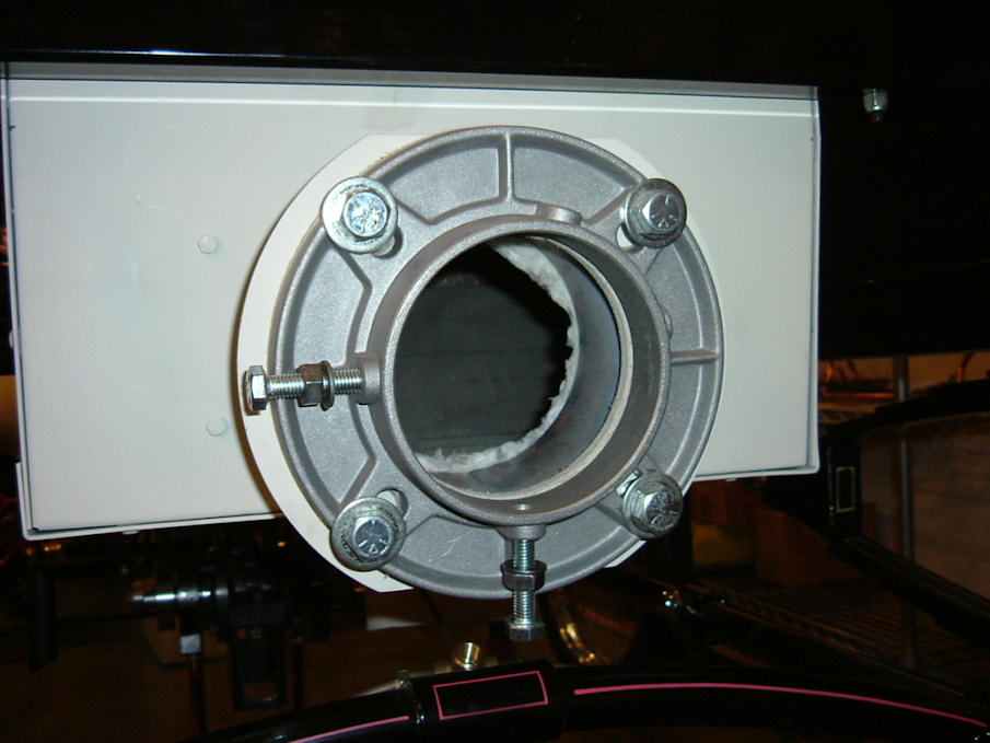
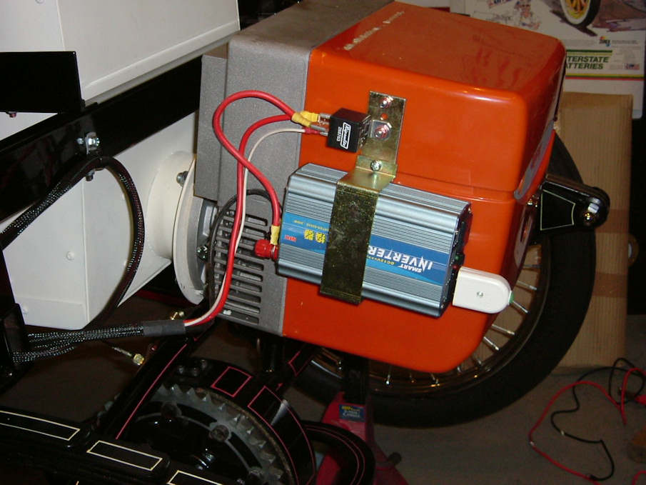
Install burner, tighten the locking bolts to secure the burner and then tighten the lock nuts. Using the Inverter bracket supplied, drill holes to mount the bracket to the outside of the plastic cover along with the relay, as the instructions direct. I changed over the terminal ends for the inverter to a proper size and used a star washer to lock in place.
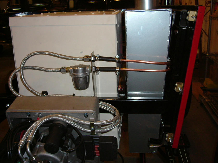
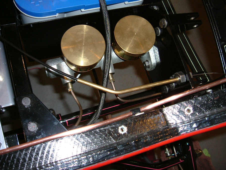
There aren’t any instructions as to how to run the burner fuel lines, only how to hook them up. I chose to run my fuel lines across the back and around the right side water tank. Making my own brackets to support the lines and filter I am quite pleased with the results. However you decide to run your lines, always keep in mind future servicing. The lines do bend easily but always use a bender or some other form while bending so as not to kink the line.
5.0 Hours
March 12
There is a threaded bung at the top of the right side water tank that can’t be used because it is blocked by the upper boiler manifold. I used a 3/8 slotted pipe plug and sealer and installed it into that hole and cut the remainder of the plug off flush with the bung. As you will find out there is very little clearance between the boiler manifold and the water tank.
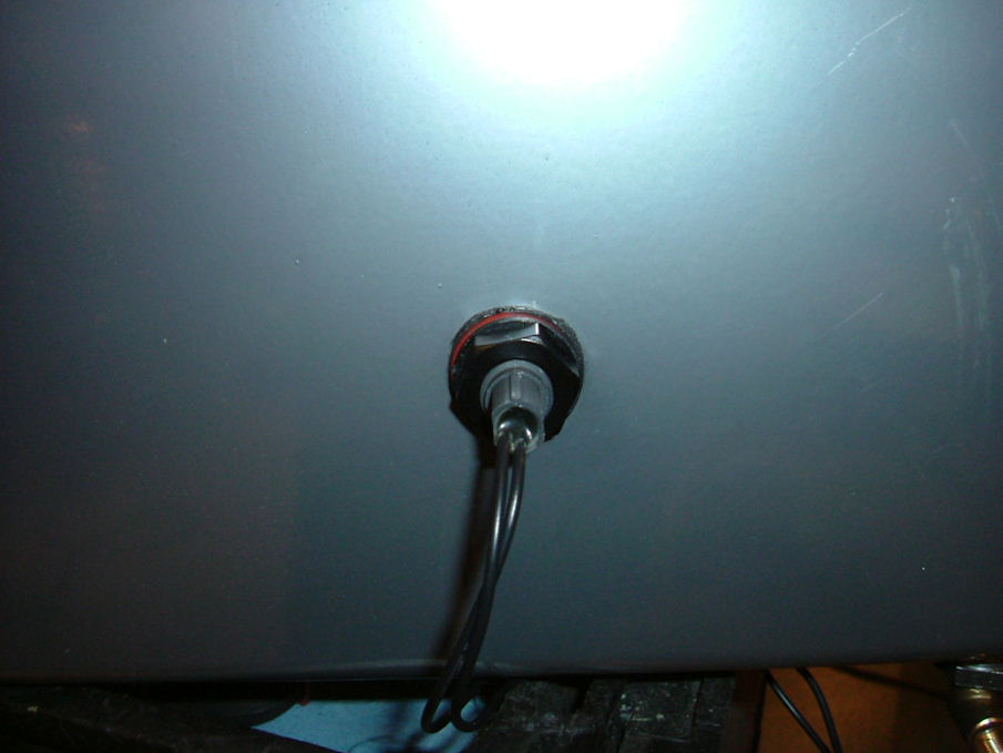
I installed the fuel tank sending unit into the tank as per instructions. An important note here; if you install the sender as per instructions the fuel light will illuminate all the time and go out when the fuel is low. This is the original design. I chose to install the sending unit 180’ of the installation instructions, so my fuel light will now only come on when the fuel is low. I would be more apt to heed a light that suddenly comes on as a warning rather than no light, which means everything is OK. To each their own.
I finished installing the fuel lines, remember that the fuel line to the bottom of the tank is the feed/ in line. I installed the return line in the top of the tank as instructed.
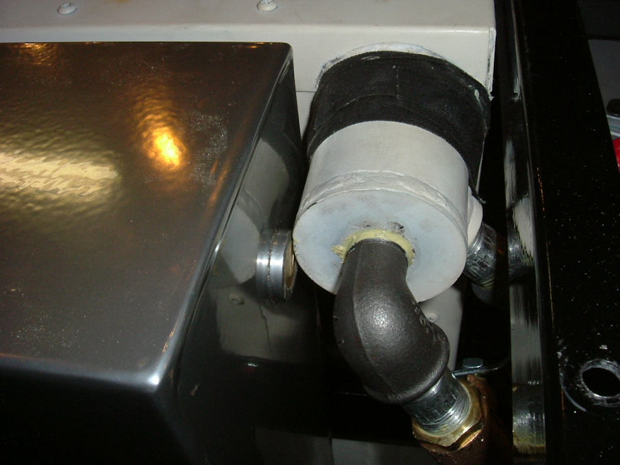
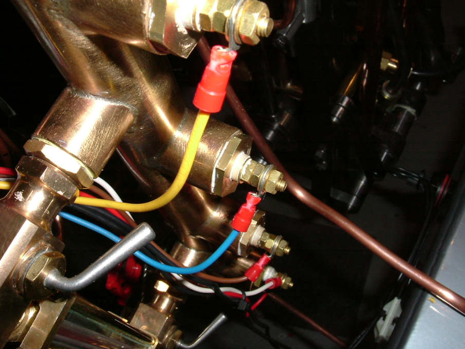
The pipe fitting to the pressure switch will not go on easy as there is paint on the switch threads. I used a wire wheel on my Dremel tool to clean the paint off the threads. Even with the paint removed it will still be tight to thread on, use some oil on the threads and carefully thread the fitting on with 2 wrenches, remove and clean threads and repeat.
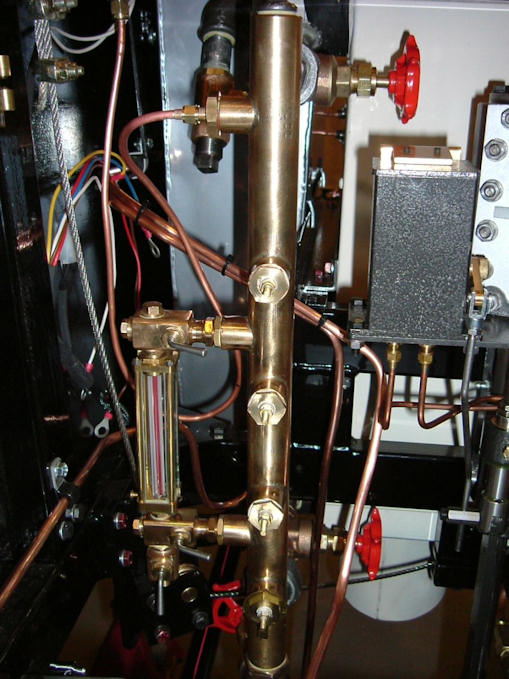
Install the yellow spring as directed, turn the adjusting screw down until 1mm below flush, this is a good starting point. The O-ring goes between the bottom of the tube nut and the flange edge, use some oil and tighten to the switch. I located my switch high on the right side, and then bent my tubing accordingly. The U bend must be made so as to protect the switch with a small cushion of water that will remain in the tube. I used a fiber washer as well as sealer on the adapter to the turret for a better seal.
4.0 Hours
March 13
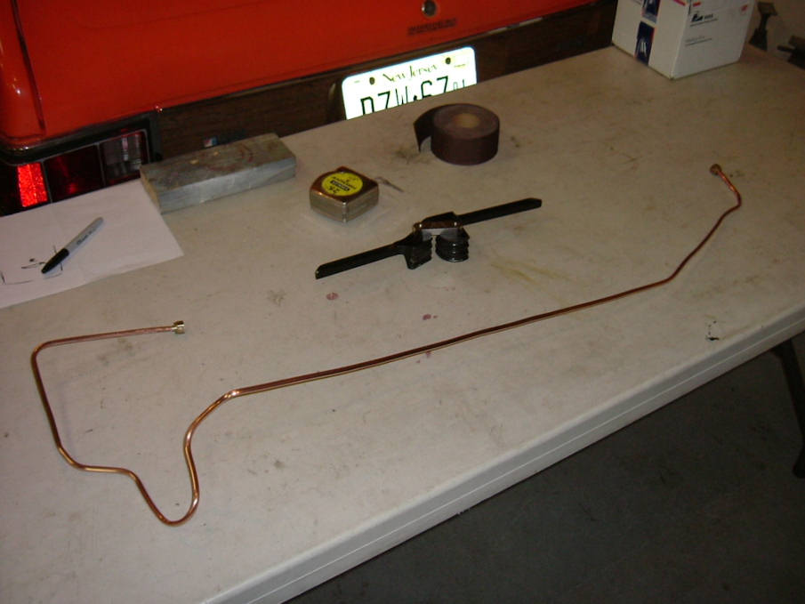
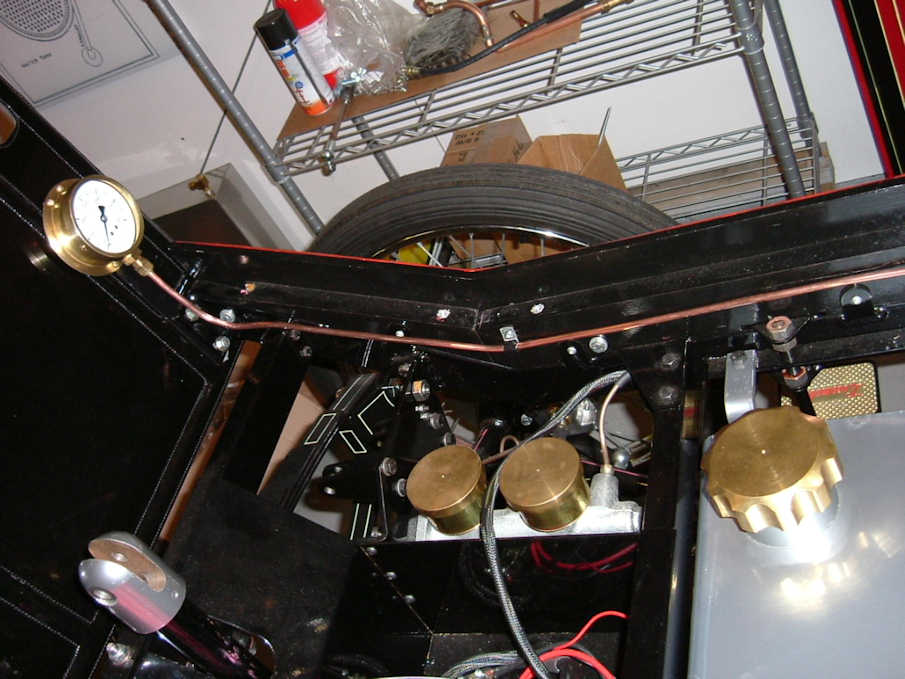
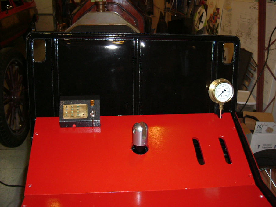
The Steam pressure gauge is designed to be screwed onto the wooden dashboard. As mine is a leather dash I made up a bracket to mount the gauge. The gauge has a small nipple that is supposed to seal into the tubing, I had to slightly enlarge the hole with a drill bit. This must be done carefully by hand so as not to damage the tube. I then configured my line bends along with the U bend and attached to the chassis with several line clamps.
I then reinstalled the water pipes that I previously removed for the boiler install.
I am running a steam whistle and I fabricated my steam lines at this time.
I installed the throttle cable and sheathing. I found that with the original spring return design I couldn’t get full throttle. I eliminated the original spring and drilled a 1/16th hole in the regulator arm and installed a universal carburetor return spring between the hole in the arm and the bracket bolt directly above it. I did install a longer bolt for the spring to have better purchase. Also; the cable is plenty long enough to run but the sheathing is a little on the short side. I drilled the throttle cable guide hole at the pedal larger to accommodate a 3/16th copper tubing that I bent slightly for a smooth cable flow. I used electrical sticky mounts on the fuel tank and tie wrapped the cable in place.
6.5 Hours
March 24
The floor board cross members required notches to be cut in order to allow clearance for the steam pressure gauge copper line and the throttle cable.
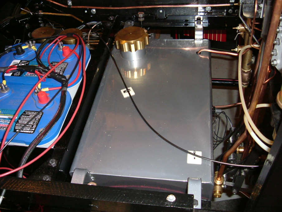
I installed my batteries, since there are studs and wing nuts provided on the Optima Batteries, I cut off the large battery terminals and used properly sized eyelet terminals instead. I added an illuminated toggle switch to my control panel for my rear running lights, also; I mounted the 2 banana plugs in the control panel for recharging the batteries.
I fitted the control panel to the front floor board and cut the notches needed for the wiring.
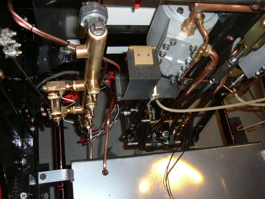
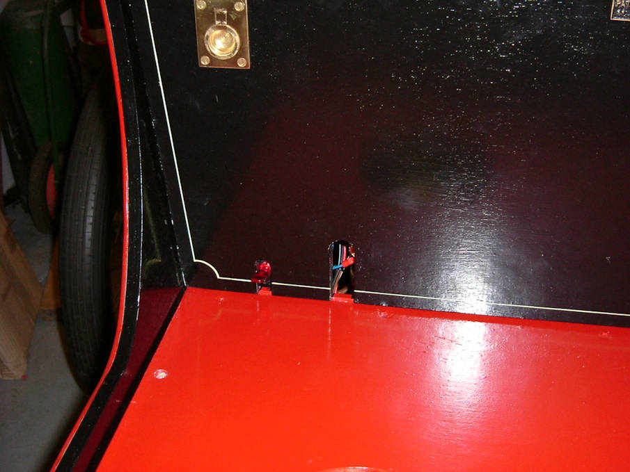
I added a master electric disconnect toggle for the main (heavy red 10guage) power to the burner. This is the red switch mounted in the existing hole in the kick board in the picture. Should something happen in the burner area, or I want to service something on the burner, I can flip the switch and turn off all battery power to the relay and inverter without having to remove the floor and disconnect the battery. I wired in my running lights and brake lights at this time as well.
The instructions have the turret sensor wiring reversed, the correct wiring for the turret and the water tank sensors are from top to bottom are: yellow – blue – brown – white –red for the ground terminal. I changed over the turret wire terminals to a smaller proper fitting size.
With everything wired, you can now test the Led lights on the control panel. Turn the key to ON, the only lights that should be on is the battery lights. I’ve been informed that the top light may not light due to the sensitivity of reading at full charge. Your fuel light will work according to how you installed you tank sensor as described previously. Using a jumper wire, hook one end to the ground ring of the turret and touch the other end to the top sensor, the top Led light should light, the other lights should light accordingly as you go down the turret. You should hear the burner relay click when you touch the bottom sensor as well as light the bottom Led light. Repeat the same test for the water tank sensors, except the relay won’t click when you touch the bottom sensor. If a Led light is on without jumping the sensor, disconnect that wire, if the light goes out then there is a short in the sensor, remove and disassemble and correct. The inner sensor should not be in contact with the outer bushing. Note: this test is assuming you haven’t filled the water or fuel tanks yet.
6.0 Hours
Fellow builders Brad Beutlich (California) and Tony Batten (UK) have there Lika’s steaming. These guys made up their own plumbing and block offs in order to get steaming right away. A lot of the information that I’m reporting is from their experiences and in no way is it final.
Brad has been in constant communication with ModelWorks acting on behalf of the US contingent. There are several changes that will be made regarding timing procedures as well as nozzle changes in the burner.
I will be reporting these changes in my next installment, as well as the Brake pedal modification, rear brake line modification, chain installation, and fuel bleeding process.
As information comes my way I will pass it on.
ModelWorks say’s that the Super heater, hand water pump and water feed line should be arriving soon.
I was a little disappointed in the instructions concerning this installation as I thought they would think this was very important and should have provided as much information as possible. Most of what I reported is information provided to Brad and myself through emails and phone calls.
Happy Building
Rick
Burner Installation.
Click here for almost complete picture
Update 2010: Modelworks are now Steam Traction World their website can be found HERE
Go to page:
Kit One and Two.
Kit Three and Four.
Kit Four B and Five.
Kit Six and Eight.
Kit Seven.
Kit Eight.
Kit Nine.
Kit Ten.
Addendum Kit Ten.
Kit Twelve.
Kit Thirteen.
Kit Fourteen.
Kit Fifteen.
Kit Sixteen.
Kit Seventeen and Eighteen.
Boiler Installation.
Burner Installation.
Leaf Spring Modification.
Engine Modification.
Brake Pedal, Brake Line, and Throttle Pedal Installation
Fuel Line Pickup Modification.
Super Heater, Hand Pump, and Plumbing.
Some Final Assembly and First Time Steam Up.
Road Test and a few Modifications.
Locomobile Cylinder Drains July 2009.
|


