| |
|
The SES Steam Car and Engine.
A Brief History.
by Stan Jakuba.
The video gives an idea of the style of car used.
Click here for short movie of 74 Plymouth.
The Project
In the early 1970s, SES Corporation of Newton, Massachusetts, won a contract to build
a steam engine car demonstrating non-polluting car engines in the United States. SES (initially an
abbreviation for Steam Engine Systems, later for Scientific Energy Systems) had built several prototype steam
power plants by that time, the expanders being a conversion of a compressor or a diesel, the feed pumps being
off-the-shelf industrial types, etc. The boilers and burners, however, were in-house designed from the
beginning, SES gaining experience while achieving the desired low-polluting combustion and, with it, patent
protection. The car project was funded and directed initially by the federal Environmental Protection
Agency and later by the Department of Energy.
This history focuses on the steam engine installed in a 1974 Plymouth Fury body and tested
on a chassis dynamometer.
The Power Plant
The working fluid was water, the fuel gasoline. The boiler containing the burner in
its center was compact enough to fit next to the expander under the hood. The only modification to the
Plymouth Fig 1 consisted of enlarging the radiator space to house the inevitably huge condenser and fans necessary
for the fully closed system. The condenser area was such that the ram air alone sufficed to cool at cruising
speeds and average air temperature. The condenser fans were operated hydraulically to enable matching their
speed to the demand thus minimizing the otherwise substantial power drain inherent with closed-loop steam cars.
It is a common knowledge with steam engines that the steam consumption, or the fuel economy
for that matter, is a function of both steam pressure and temperature. While the high pressure gain diminishes
beyond a certain limit, the temperature increase is theoretically beneficial to no end. The SES system was
designed to the practical limit of both parameters, settling eventually on 1000 psi and 1000 ºF to the expander
inlet at all times.
All the controls were fully automatic; the driver needed only to “turn on the key”
and in about 20 seconds the car was ready to move, the expander idling and capable of driving all the auxiliaries
and accessories (including air conditioning. Was this the first air-conditioned steam car ever?). An
automatic transmission enabled the familiar P R N D selection. About 45 seconds were needed to have the full
power available at the wheels.
The power required for the EPA-specified carrying capacity, speed, and acceleration lead to the
need for about 100 kW mechanical output, and that scaled the size of the engine components.
The Expander
The expander configuration was decided upon weighing the many criteria inherent in the passenger vehicle application,
alongside the usual steam-related options. The two drawings Fig 2 & Fig 3 show the final design: an in-line
4-cylinder, single-acting with trunk pistons, uniflow with poppet valves. The bore and stroke of 89 mm each provided
ample displacement. Ample meaning that it turned out rather oversized for the automotive duty as was concluded a
couple of years later. See the table at the end.
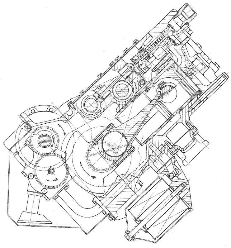
Fig 2. The L-4 prototype expander shown in transverse cross section.
The expander could deliver more power than needed at the rated 2500 rpm. It could also run much faster quite
nicely as was noticed on the occasion of its output shaft shearing during one of the full-power tests.
Steam admission was cut-off controlled, the mechanism consisting of two poppet valves in series, each operated by
its own camshaft. Steam would enter the cylinder when both valves were opened. The variable admission was
accomplished by phasing one camshaft against the other via a hydraulic mechanism, its position controlled by the
accelerator pedal. The in-series scheme offered two possible arrangements: the admission could be closed by
the valve closer to the cylinder or vice versa. The difference mattered in handling the discharge of the steam
trapped in the inter-valves passage. Initially, a less efficient arrangement was selected where the volume
of steam between the two valves did not discharge into the cylinder. It was calculated that even at zero cut-off,
this small volume of steam would deliver too much power for idle. Tests revealed that the parasitic losses in
the actual car required more power than this provided, and so a reverse arrangement that would result in better
efficiency was happily instituted during the later stages.

Fig 3. The L-4 prototype expander in longitudinal cross section. The step-up gear assembly, visible protruding
from the flywheel, was eliminated in the final version.
Lubrication was by oil-in-crankcase. Special lubricants with additives, and materials for
the cylinder liners and piston rings, were developed with the help of subcontractors, such as Exxon, to handle the
high temperature in the presence of steam. (See Foot-Note) Employing the trunk piston rather than a
crosshead design (to save space and mass) necessitated oil/water separation. The crankcase blow-by separation
was neatly incorporated in the camshaft phase change mechanism thus taking no extra space or adding mass.
The cover of the mechanism is visible at the “nose” of the expander, above the crankshaft front
end. As luck would have it, exhaust steam/oil separator proved unnecessary (imagine the size of it!) as the
condenser effectiveness was not impaired by any of the oils tried. An oil/water separator would reclaim the
oil from the liquid stage. Nor did the boiler mind somewhat oily water – there never were any deposits
in it, even with gross over-oiling. The high velocity of the minimal water inventory in circulation undoubtedly
contributed to the cleanliness.
Drive Line Concerns
To limit the vibration caused by the reciprocating masses, a counterbalance shaft was employed,
positioned in the crankcase. To increase the rpm of the output shaft and lower the maximum torque delivered to
the transmission, a planetary gear set was incorporated into the flywheel. And to protect the gear-set from the
inherently high torque peaks of the re-compressing expander, a torque fluctuations damper was placed at the flywheel.
These latter devices did a good job of speeding up and cushioning the drive train but unfortunately they
themselves could not take it. In a bold move, both were eliminated in the final version when it was found that
the car drive train itself was torsionally “soft” enough to withstand the torque fluctuations. And
a change in the rear axle and the transmission gear ratios took care of the loss of rpm with the result that the
step-up gear set was relegated to the bin of unnecessary precautions.
The reader might well wonder why there was a transmission used in a steam-engine car in the
first place. The gear change was necessary to meet the acceleration and the maximum speed specification.
That spec reflected the muscle-cars era mentality - remember the rubber burners? As torquey as every steam
engine is known to be, it still lacks power at low rpm. There was no way to meet the specs without a gear
change. And in any case, a direct drive was impractical with the accessories and auxiliaries that were to
run all the time, nor was it feasible to squeeze in an auxiliary engine for that function let alone struggle with
the resulting complexity of two power plants. A stock automatic transmission was a proven solution, and was
also cheap since Chrysler Corp. was a subcontractor.
Burner, Boiler, Feed Pump & Controls
The burner and boiler were developed as one unit Fig 4 that would provide a combustion chamber shape
suitable for the homogenous gasoline-air mixture to be burned with near zero pollution. The burner fan was
hydraulically driven, air and fuel flow both controlled independently to match the power demand and the low emissions
demand. The turn-down ratio was 20 to 1, and the “throttle” response, to use the IC engine terminology,
exhibited no appreciable lag going from idle to full power. This boiler with its burner was described in
the Bulletin several years ago.

Fig 4. The longitudinal cross section of the boiler/burner assembly.
An in-house developed feed pump was driven from the expander directly and could deliver zero
to max available flow at any speed without by-passing. It had solenoid-controlled inlet valves, one with each
of its three plungers. A power input minimizing arrangement, this feature also allowed drainage for freeze
protection.
The instantaneous zero-to-full flow was a nice feature, as with the monotube boiler of
essentially no water reserve, the controls proved a nightmare when trying to get everything adjusted right and
fast. As said, water flow, gasoline flow, air flow, condenser back pressure, steam inlet temperature and
pressure were all automatically adjusted without driver’s input other than the movement of the accelerator pedal.
The electronic control assemblage took up the trunk space in those pre-computer days. Most components
were standard laboratory control modules, since the development of dedicated controls was not within the scope of work.
The Performance Map
In the final stages of the program a complete performance map of the power plant was drawn,
calculated from the measured data. It has not been published before because, as often happens, projects die
without much trace when funds run out and interest wanes. The years past the 1973 oil embargo were not
favorable for funding steam cars. The term “mpg” came into general use. The mpg of this huge car was
respectable but still a thorn in the DOE image. After the car was tested demonstrating that it met the specs
then the funds were directed to fuel economy improvements, a program that encompassed every aspect of the power-plant
and drive-train including auxiliaries and accessories. The performance map is presented here for posterity
and therefore it is in SI units to be easy to use by the next generation of steam nuts when the time comes again
to revitalize steam engines for transportation. The DOE overseers also required the use of SI metric units.
The map allows predicting the performance of reciprocating steam plants of a wide range of
sizes and power as long as the expander is of a similar configuration and the steam pressure and temperature are
similar. Interestingly, temperature had little effect on performance in the range above some 750 ºF. Thus
the map can be reflective of also 800 ºF or 900 ºF as the rated 1000 ºF. Certainly, SES could have saved
itself lots of headaches had it known this from the beginning, because lowering the temperature while receiving
the same performance would have eliminated much of that expensive research into exotic lubricants and wear
properties. Lower temperature would have also made the use of the finicky throttle valve easier, a valve
that was hoped would not be necessary but in practice the fully automatic control was too difficult to achieve
without it. It also turned out that, contrary to the data of specific steam consumption obtained on a
dynamometer, overall efficiency did not suffer all that much in the car, even improved for some operating regimes,
at a lower than 1000 psi inlet pressure.
In the chart Fig 5, on the vertical axis, BMEP stands for Brake Mean Effective Pressure. It
is a measure of what’s commonly called “load” and it indicates how hard each unit of volume of steam in the cylinder
works, that is, how well the engine utilizes its displacement volume for producing power. On the horizontal
axis, MPS stands for Mean Piston Speed, which is a parameter akin to rpm except that it is universal for all
reciprocators. With the SES expander, as an example, 7 m/s is about 2400 rpm or 40 rps.

Fig 5 The performance map of the car power plant.
BSFC and BSEC stand for Brake Specific Fuel Consumption, and Brake Specific Energy Consumption,
respectively. The BSFC is in grams of fuel per unit of work produced in propelling the car (g/MJ); it is a
measure of how much fuel is needed for a unit of that work. The BSEC is a measure of how much energy is
needed for a unit of that work; it is a ratio of energy (rather than the mass) in fuel vs. the useful work.
Unlike the BSFC, BSEC is universal for any fuel, be it kerosene, propane, natural gas, or gasoline. To figure
out the fuel mass flow, all one needs to know is the specific heat content of the fuel in question (it is 44 kJ/g
with gasoline).
On the right-hand side are the numbers for Cut-Off and for VER. The Cut-Off is in crankshaft
degrees. The VER stands for Volumetric Expansion Ratio, the ratio of the total volume in the cylinder divided
by the volume at the point of the inlet valve closing. It is akin to “percent cut-off” but it includes the
impact of the clearance volume.
Finally, the 1, 2, and 3 W/mm2 lines (P/Ap) provide a measure of how much power one can expect
from a unit of the piston area. It looks like about 2.2 W/mm2 would be obtained in the best efficiency region.
With this graph, one can estimate the performance of similar engines, as said. It shows
that, for example, the best fuel economy corresponds to the MPS of 2.5 to 4 m/s and VER of 7.5 to 4.5. This island
of the high efficiency is quite broad indicating that efficiency was not all that sensitive to those parameters.
Geared to run at the same cruising speed with only 900 rpm (and 55º cut-off) or 1400 rpm (and 30º cut-of), the fuel
consumption would be about the same, as it would be for all points along the 2.2 W/mm2 curve within that best BSFC/BSEC
island.
Lastly, readers might be interested in the heat balance of this engine. As with all car
engines, this one would also run at partial load most of its life. The table Fig 6 shows the distribution of
power in kW and % of fuel energy for three cruising speeds. A post 1973 spec might have focused more on low
consumption at these conditions, and that would have lead to a smaller and cheaper engine.

Fig 6 The power-plant’s heat input, mechanical output, and losses at partial load corresponding to three cruising speeds.
Foot-Note
I should like to add for the British readers; the expander, the basic design and manufacture,
was done mostly by the Ricardo Engineers, Shoreham by Sea, U.K. and the pistons were designed and cast by Wellworthy
Piston Rings Ltd, Lymington, U.K. SES subsequently designed and built modifications to the Ricardo hardware
based on the test results, and abandoned the Wellworthy pistons entirely. The article mentions ExxonMobil as
a subcontractor; Ricardo should be there too. Nobody in the US would have appreciated such an "unknown" (in
the US) as Ricardo, but GB readers undoubtedly know the company and its founder (I have a book signed by Sir Harry).
The step-up gear, shown protruding from the flywheel, was actually a backwards installed,
step-down, marine, planetary gear manufactured in England for boat propellers. It came to us assembled and
mounted in the expander. After some month of testing, during a routine teardown and inspection of all components,
we noticed that the holes drilled radially into the output shaft for bringing oil to lubricate the gears were
elliptical. This caused quite a stir among the Yankees for they were trying to figure out the advantage of
flowing oil thru elliptical rather than round holes as was common in the U.S. Concern was also raised as to the cost
of the elliptical holes and the budgetary consequence of the non-round drilling. While still pondering a few
months later, during a full load test, that shaft sheared as mentioned in the body of the article. Upon disassembly,
it was found that the holes were more elliptical yet, and that the shear occurred right thru the most distorted hole
of them all. Thus we never learned how to drill elliptical holes.
It may be of interest to you that the final car does not look like the Fury. That model was out of
production by the time the project progressed to the in-car stage. The car current at that time was the Dodge
Monaco and that's what the car looks like. Readers relying on the Plymouth video could question the portrait if
(ever) the car is at a public accessible location.
Stanislav Jakuba.
Click here for wobble-piston type engine.
|
|