Kit Thirteen.
August 21, 2006
Fit the steering stop as described. A very nicely engineered piece, but I found that the stop limits the turning radius quite a bit and I felt the stop would not prevent the crushing of the brake lines should a wheel catch a pot hole and possibly bend the tie rod. I fabricated a simple set of stops that would prevent line damage and not limit the steering as much. The following is how I approached this: I performed the modification one wheel at a time.
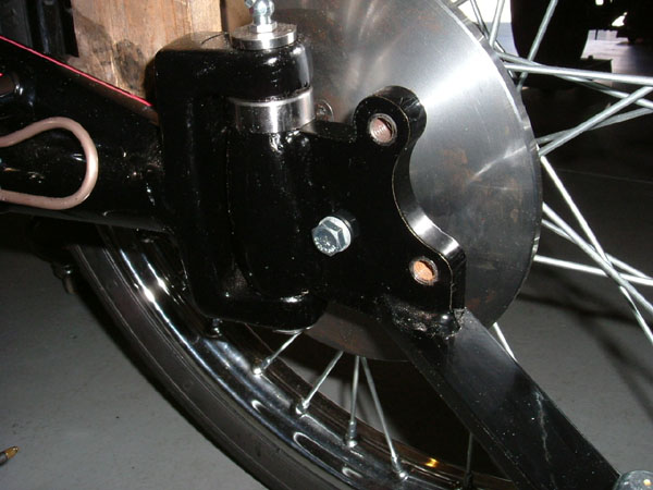
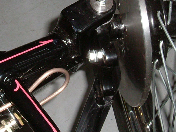
1. Remove caliper and let hang off to the side, remove tie rod end clip and disconnect end. Place masking tape on the caliper bracket, turn spindle to contact the axle, mark this location.
2. Turn spindle to full opposite turn, this gives plenty of working room. Center punch and drill a hole 17/64" completely through, tap this hole with a 5/16x21 tap. Take your time, use oil on the tap, turn the tap ¼ turn clockwise then 1/8 turn counter clockwise to clean debris, after a few turns remove tap to clean debris. Continue until entire hole is tapped through.
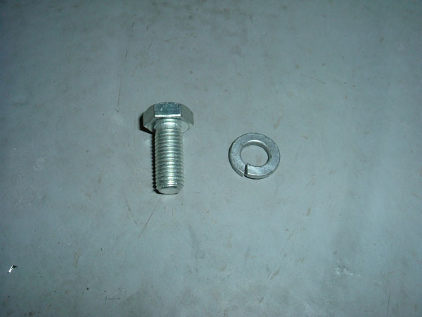
3. Reassemble tie rod end and caliper, thread in a 5/16x21x3/4 bolt. (8mm bolt will work fine, just drill and tap to bolt specs) Turn wheel until the brake line interferes with itself. Turn out the bolt until it touches the axle and then ½ turn more. The amount of thread exposed is the amount of washers you will need to use. My car required 2 lock washers. Each car will be different so experiment so your lines don't interfere. This is a positive stop at the spindle/axle instead of at the steering mechanism.
4. Repeat on the other side.
2.5 Hours
August 27
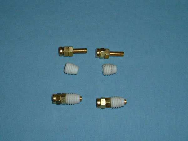
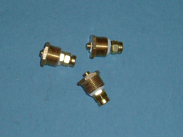
I found the assembly of the water indicators to be extremely tight. The brass screw would start to strip in the nylon while installing the nylon into the brass bushing. Note: there are a lot of brass filings on the bushings, so clean everything thoroughly. I double nutted the brass screws and threaded the screws into the nylon bush. I put the assemblies into the freezer for about 2 hours, (I got this suggestion from Brad Beutlich in California as we were discussing this part of the build) I lightly coated the nylon threads with a liquid Teflon thread sealant (Permatex # 765-1188 from Napa). Using a suitable device to hold the brass bushing, I threaded the nylon bush in using a 10mm wrench on the nuts. It now goes in quite easily. Unscrew the brass bolt assembly, clean off the excess sealant; assemble the indicators as directed using the sealant. Install into the tank as instructed.
2.0 Hours
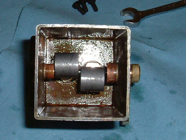
With tanks back in the chassis I installed the water balance plumbing. I chose to install a plumbing gate valve instead of the chrome drain cap. This way I can drain the water tanks with a twist of the wrist. See pictures.
1.5 Hours
September 9
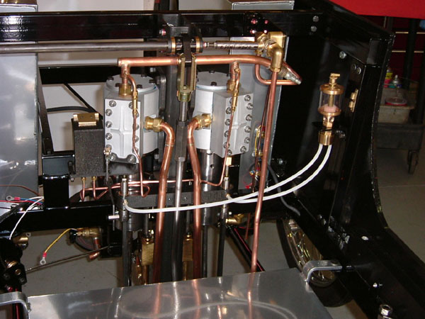
Assemble lubricator assembly, and modify the mounting bracket as instructed in kit 11. Note: do not over tighten the brass half nuts, as this will create a distortion of the ram assembly. I used a little bit of sealant on the base of the ram assembly. The lid and hinge can be assembled incorrectly if you don't pay attention to the threaded holes in the hinge lid. The lid must seat completely flat on the lubricator body of else you will have oil spillage.
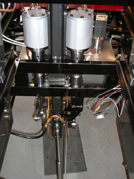
I ran my oil pipes as neatly as possible as directed. Installed the drip feed oiler, making sure the sight glass and filler hole was facing the front of the car. I carefully heated the nylon tube with a heat gun to get the desired shape always continuing a downward flow.
Installed wiring loom as directed.
4.5 Hours
The instructions, ISO drawings, and pictures help to make assembly a bit easier. I was truly impressed with the lubricator; this was the fun part of this kit for me. A nicely engineered piece that smacks of real 1900 automotive engineering. Keep up the good work.
Brad Beutlich and I have been collaborating on accessories for the Likamobile; some of these have been already incorporated into our cars as we have been building them. Read some of the past kit builds. We have a few surprises in the works to help dress up our cars and have fun with.
Happy Building
Rick
Kit 13.
Click here for almost complete picture
Update 2010: Modelworks are now Steam Traction World their website can be found HERE
Go to page:
Kit One and Two.
Kit Three and Four.
Kit Four B and Five.
Kit Six and Eight.
Kit Seven.
Kit Eight.
Kit Nine.
Kit Ten.
Addendum Kit Ten.
Kit Twelve.
Kit Thirteen.
Kit Fourteen.
Kit Fifteen.
Kit Sixteen.
Kit Seventeen and Eighteen.
Boiler Installation.
Burner Installation.
Leaf Spring Modification.
Engine Modification.
Brake Pedal, Brake Line, and Throttle Pedal Installation
Fuel Line Pickup Modification.
Super Heater, Hand Pump, and Plumbing.
Some Final Assembly and First Time Steam Up.
Road Test and a few Modifications.
Locomobile Cylinder Drains July 2009.
|


