FINAL, FINAL, FINAL KIT – MOST LIKELY
April 30, 2008
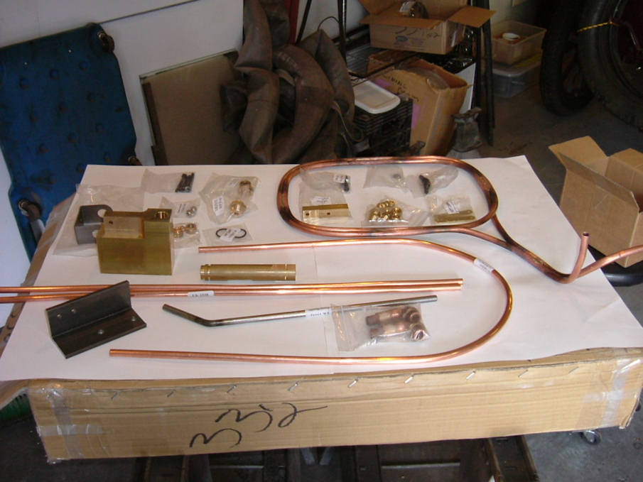
The final box of parts shows at my door. Went through the inventory of parts, and read the instructions to familiarize myself with the assembly and figure out how I’m going to approach this segment.
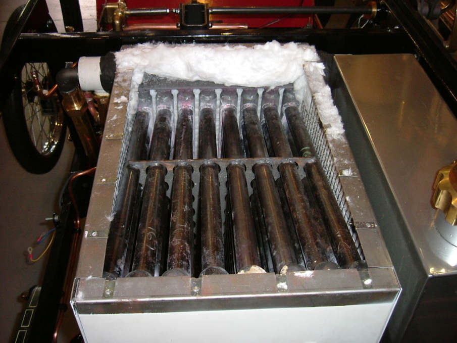
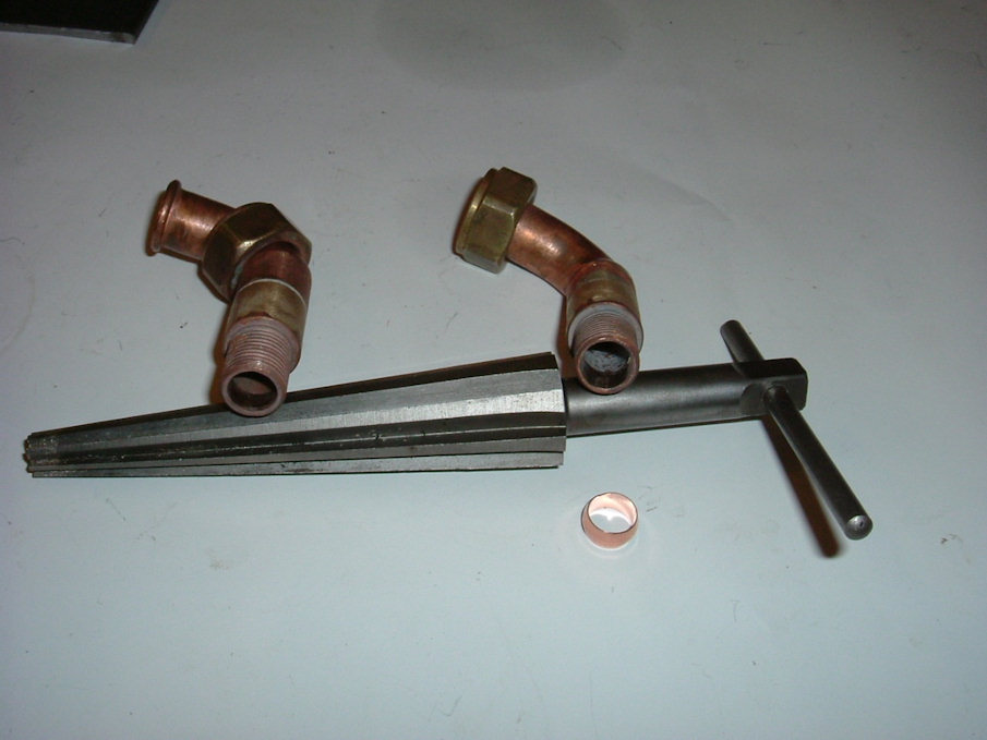
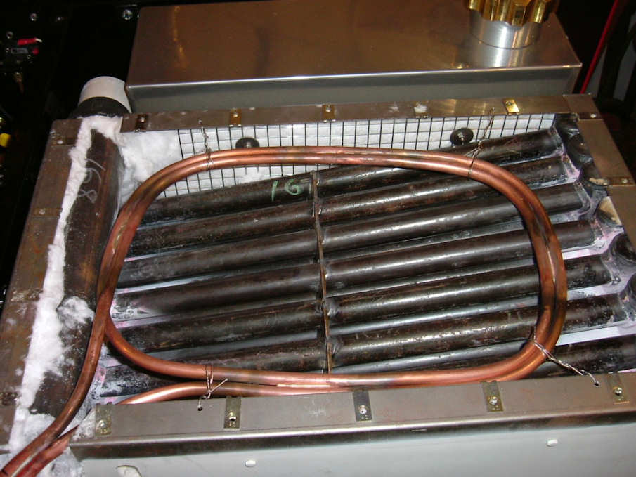
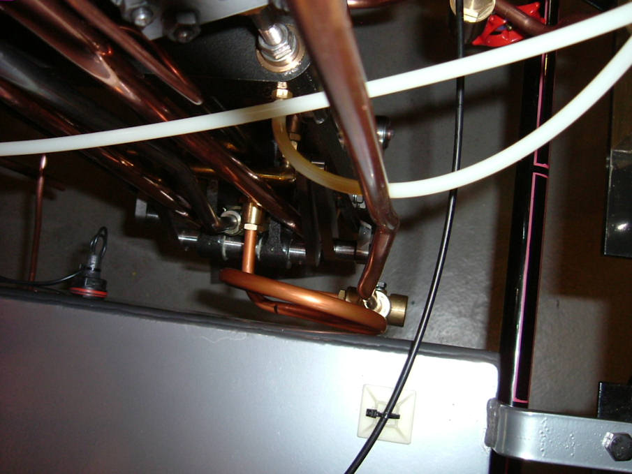
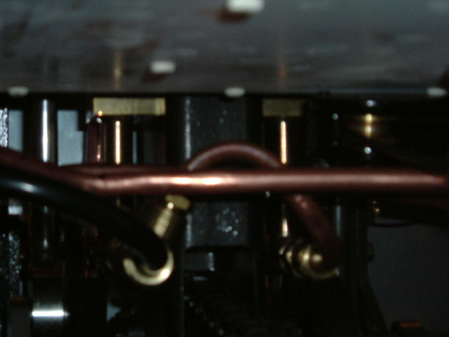
Remove the L/S water tank and the top of the boiler cladding. I positioned the super heater as shown in the pictures. Note that the pipes do not go through the oval hole originally provided, but over the boiler manifold and between the upper chassis rail and manifold. I loosely installed the elbows on there respective fittings and bent and finessed the tubing to meet the elbows. Remember to use a form or bender when bending tubing to prevent kinks. I had to remove/ install the super heater about 10 times to get it right. I used a tapered reamer on the elbows where the compression fitting is supposed seat, (the elbow had no taper at all) I reamed the tube just enough so the compression sleeve will be guided into the elbow when tightening. The super heater fit nice and snug, I had to remove about ½ inch from the regulator side of the super heater tubing to make it fit right. Do not tighten any of the elbow fittings until it fits just how you want it.
With the elbow fittings tightened, I finessed the super heater coil into the center of the boiler. I drilled 4 small holes into the side lips of the boiler cladding and used stainless safety wire and safety wired the super heater coil to the cladding so it won’t bounce around and cause the tubing to crack in the future.
The emergency blow off tube is now located almost vertical and just fits between the chassis and the lower boiler manifold.
Cut the boiler top cladding just enough to clear the super heater tubing. I made a block off plate to cover the original hole where the super heater was supposed to go. Install the extra insulation as needed. (Use rubber gloves) Install the top boiler cladding with the screws previously used.
4.0 Hours
April 1, 2008
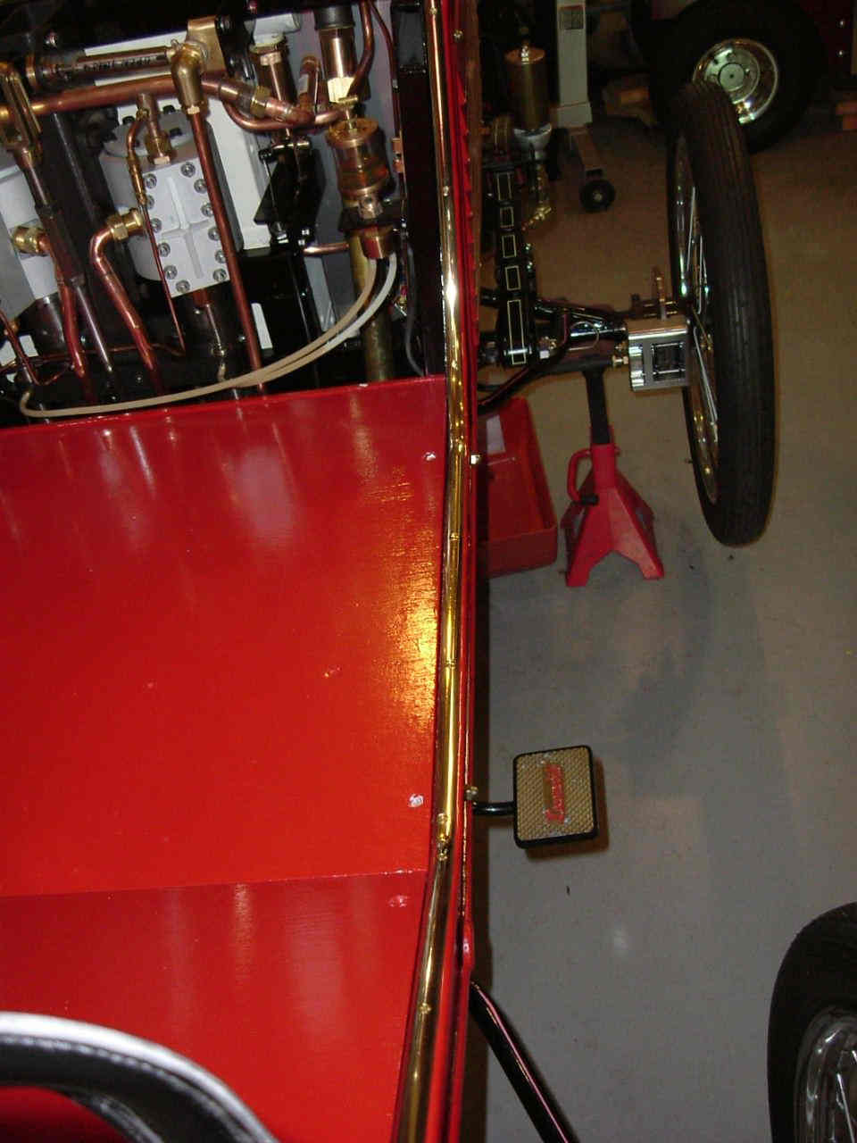
Build the water pump as per the instructions; I had to hone the body slightly for the ram to slide in/ out without binding. Note: the o-ring is installed after the ram moves freely, as the o-ring will create resistance. Upon installation into the chassis you will notice that the handle end of the pump interferes with the kick panel. Remove about a 1/8 inch of material from the ram handle end, this will provide the clearance necessary so as not to interfere with the kick panel.
2.0 Hours
May 2
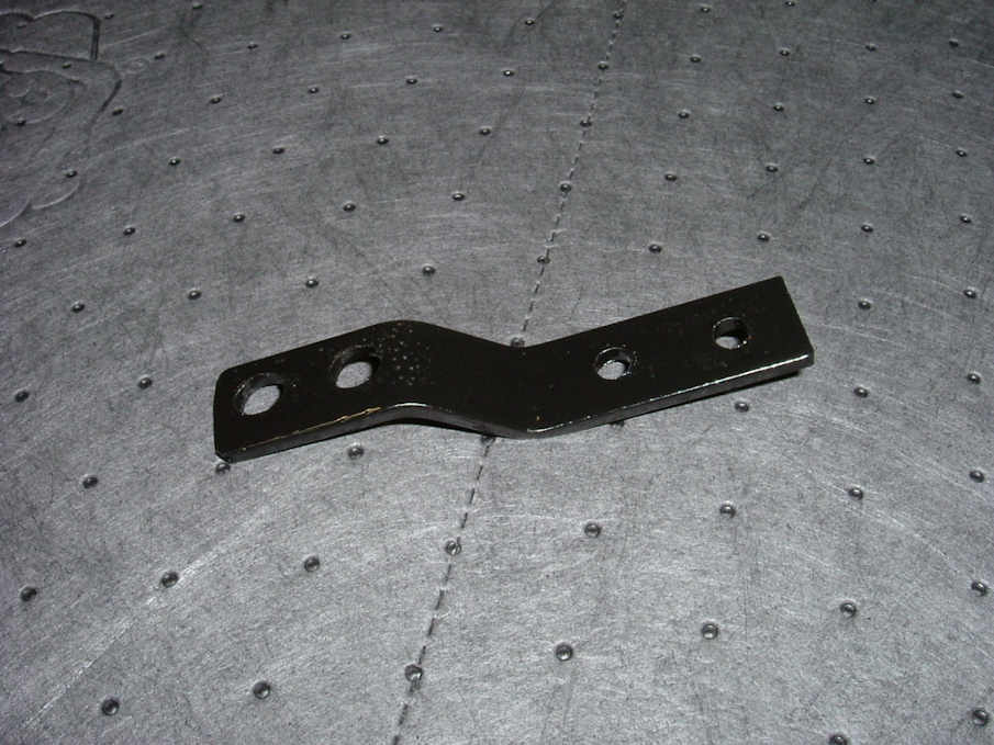
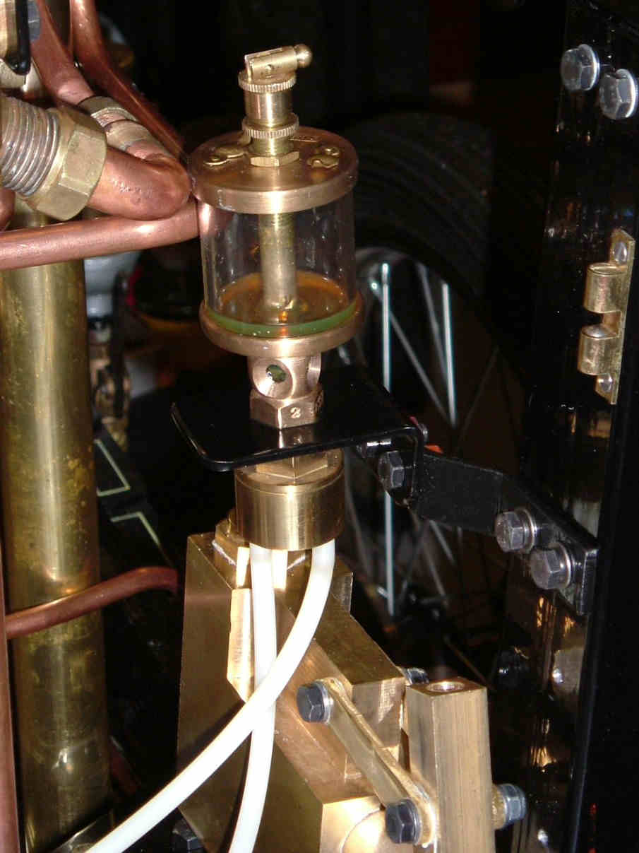
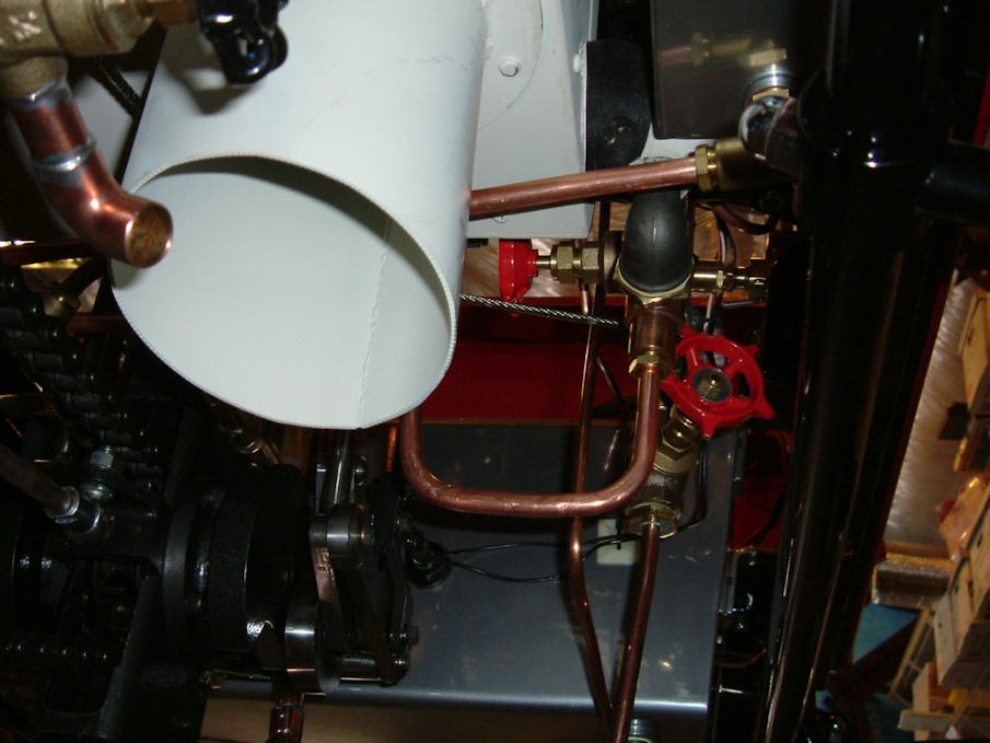
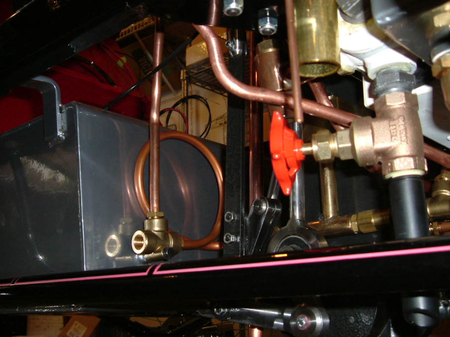
The drip oilier has to be moved or removed as per ModelWorks. I made up a zee bracket and mounted the drip oilier inward and back to clear the hand pump.
Bend and install the hand pump water tubes, I routed mine behind the engine frame above the chain, see the pictures.
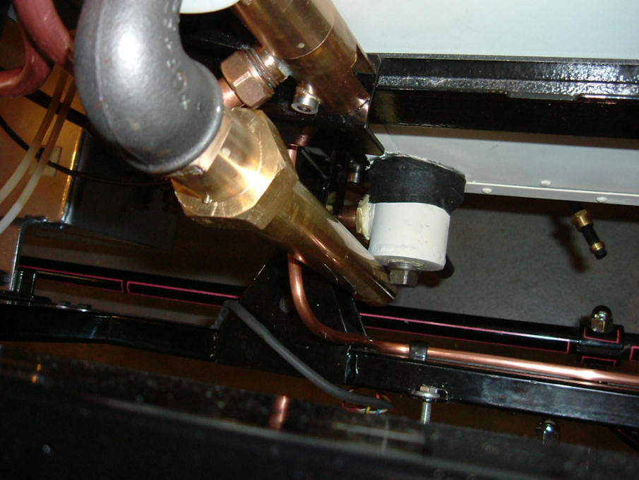
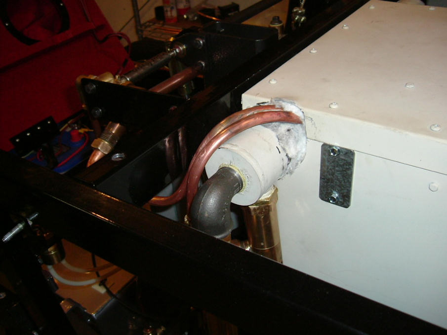
The vinyl water pump tube from the mechanical pumps to the tee (mounted on the fuel tank) will have to be replaced. It has been discovered that the vinyl tube will split eventually due to the heat and pressure. I changed mine over to copper, curled, to allow vibration and possible movement. This is a 10mm tubing, In the US we can use 3/8 inch copper tubing with 3/8 compression sleeves and the 10mm tube nuts supplied. Bend and route the tube from the tee to the boiler check valve. Reinstall the water tank and attachments.
3.0 Hours
May 5
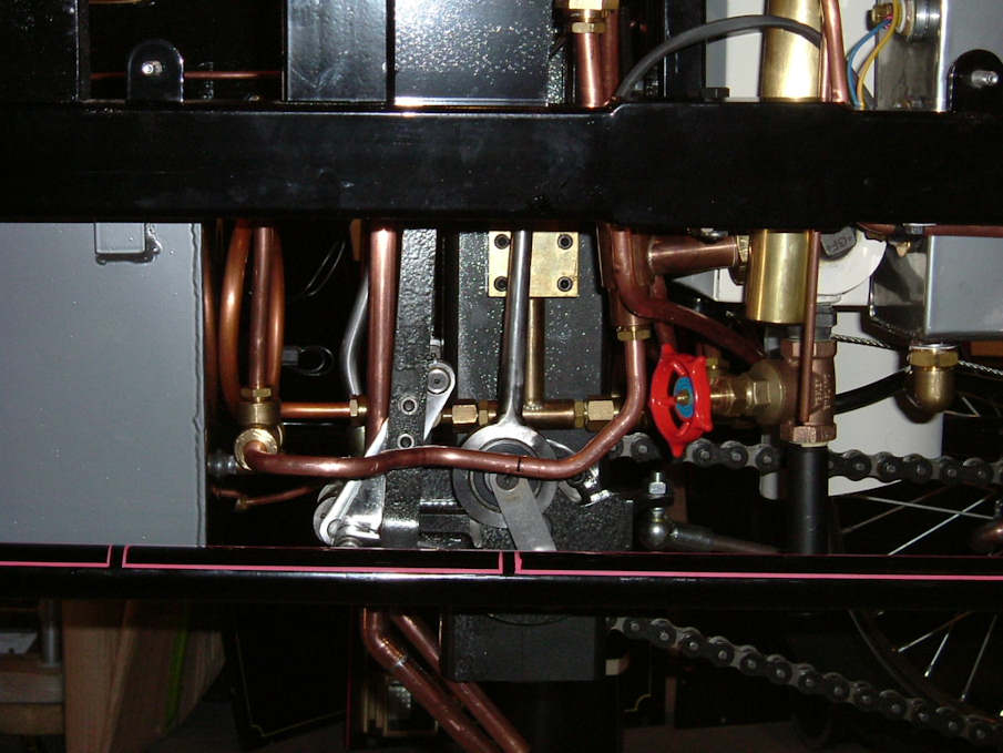
The timing of the valves has changed from the original instructions; the original set up gave the car a lot of power in reverse and mediocre power in forward. The following instructions are the latest and proven to be the best so far. Also; it has been found that the slide valves have been colliding with the steam chest corners and causing damage to the valve train. That remedy is simple and since we are readjusting the timing, not much extra effort is required.
If you have already set your timing as per previous kit build; you will have to remove the steam chest covers, put at least 4 nuts back on to hold each steam chest in place. The following steps must be made in order.
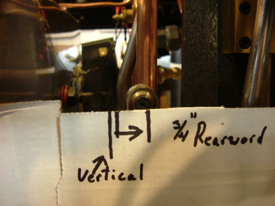
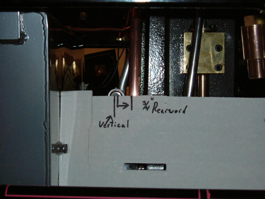
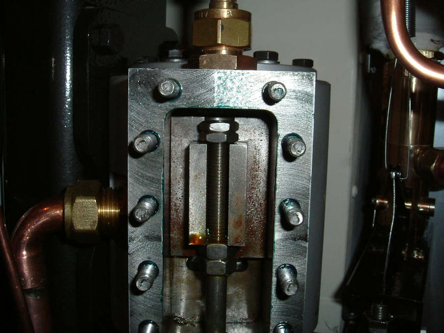
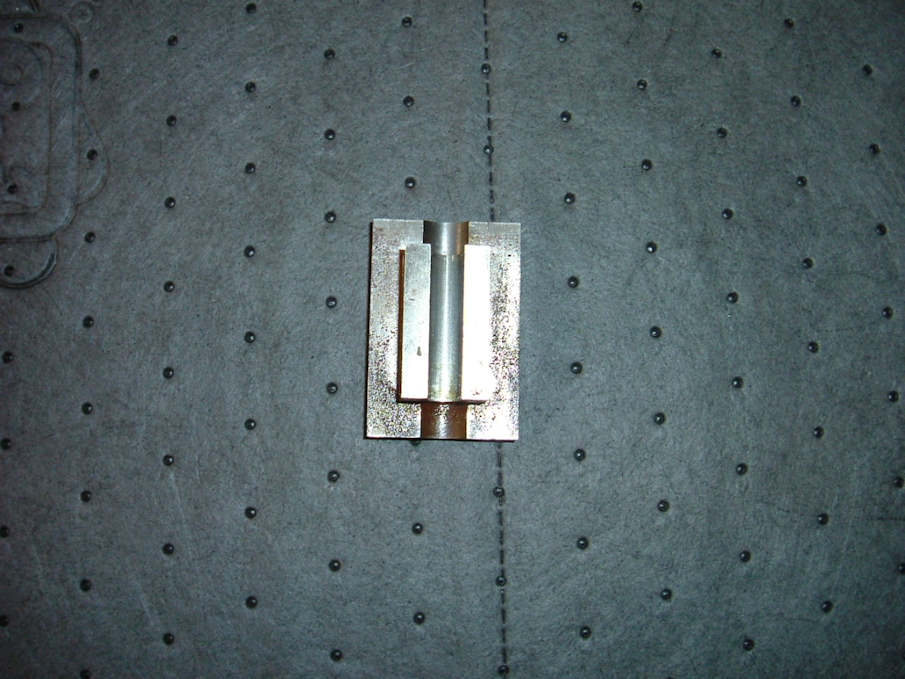
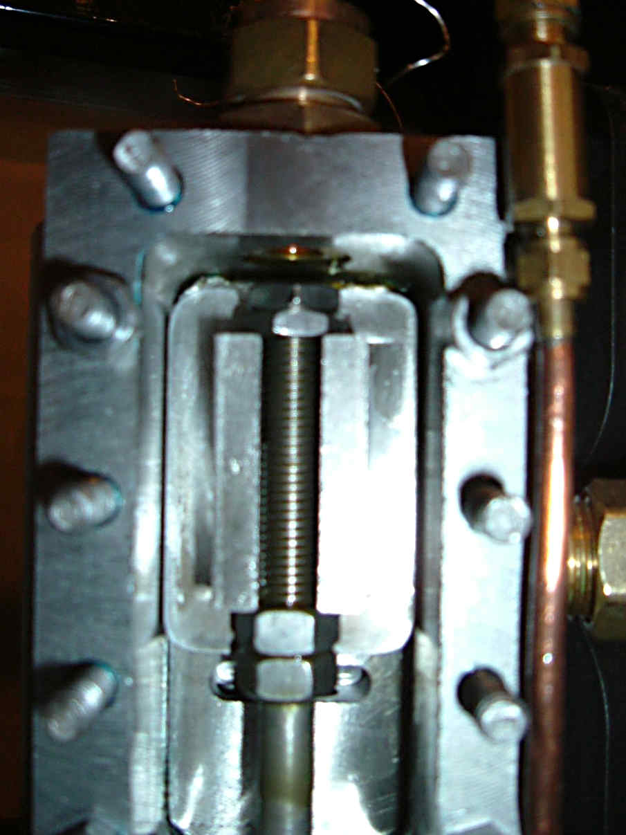
1. Place the directional lever in the neutral position; this is the middle notch of the full quadrant. Loosen the lock nuts on the reversing shaft; this is the large rod in front of the engine, connecting the quadrant control shaft at the top of the engine to the valve control on the bottom of the engine. Rotate the adjustment sleeve so the valve reversing arm (this is the arm we changed twice) is exactly straight up while looking at it from the side. (See pictures) Rotate the adjustment sleeve again so the valve reversing arm is now exactly ¾ inch back toward the engine. Tighten the lock nuts.
2. Place the directional lever in the full forward notch of the quadrant. Rotate the engine in a forward direction to bring the crankshaft and the piston to the top dead center position. Never back the rotation if you went past the position, go completely around again if necessary.
3. At this point we will remove the slide valve on the side we are timing. Remove the shoulder bolt connecting the valve guide to the valve rod. Loosen the 2 lock nuts for the valve shaft to the valve guide, loosen the 2 lock nuts on the top of the slide valve, loosen the packing nut for the valve shaft, and back out the valve shaft bushing from the valve chest. This will allow the slide valve to fall to the bottom of the steam chest, remove the 2 lock nuts from the top of the slide valve; the valve shaft will now be able to fall down enough to allow you to lift the slide valve out. Radius the corners of the slide valve and clean any sharp edges that may have been created. On a perfectly flat surface, glass, and with some 600 grit paper reface the bottom of the slide valve. Reinstall the slide valve, the shaft bushing with sealer, install the packing nut loosely, reinstall the shoulder bolt for the valve guide and rod, reinstall the 2 locknuts on the top of the slide valve and adjust these so there is almost zero lateral movement between the lower and upper nuts but the valve is free to move against the cylinder face. Tighten lock nuts when satisfied. Back to setting the timing.
4. With the piston in the top dead center position as in step 3, adjust the slide valve so the opening space of the steam port is the same on the top and bottom. This adjustment is made by turning the valve shaft in or out of the valve guide. Lightly lock the nuts of the valve guide. Rotate the engine in the forward direction 180’ to bring the piston to the bottom dead center, check the slide valve openings, and adjust to be equidistant as before. What you trying to obtain is the same amount of port opening when rotating from top dead center to bottom dead center. When you are satisfied, secure the locknuts on the valve guide. Don’t be surprised if the R/S valve openings are greater than the L/S, most everyone’s are. This does not reflect on engine performance.
5. Repeat the same procedure for the other side valve.
6. Make sure the packing is in the packing nut and tighten. Put sealer on the steam chest cover and secure with the nuts and washers as before.
5.0 Hours
May 6
I installed the brass side trim onto the panel, this requires cut to fit. I used brass oval head wood screw for the installation, about 10 per side, countersunk for a neat appearance. Polish the brass for a classy look.
2.5 Hours
At this point I am ready to install fuel and water and test fire the boiler. I will report on what happens on the next installment.
Happy Building
Rick
Super Heater, Hand Pump, and Plumbing
Click here for almost complete picture
Update 2010: Modelworks are now Steam Traction World their website can be found HERE
Go to page:
Kit One and Two.
Kit Three and Four.
Kit Four B and Five.
Kit Six and Eight.
Kit Seven.
Kit Eight.
Kit Nine.
Kit Ten.
Addendum Kit Ten.
Kit Twelve.
Kit Thirteen.
Kit Fourteen.
Kit Fifteen.
Kit Sixteen.
Kit Seventeen and Eighteen.
Boiler Installation.
Burner Installation.
Leaf Spring Modification.
Engine Modification.
Brake Pedal, Brake Line, and Throttle Pedal Installation
Fuel Line Pickup Modification.
Super Heater, Hand Pump, and Plumbing.
Some Final Assembly and First Time Steam Up.
Road Test and a few Modifications.
Locomobile Cylinder Drains July 2009.
|


